Computational design · Experiment · 26 October 2026
From cells to timber: growing a pavilion
What if you designed the growth rules before you designed the pavilion? This experiment connects cellular automata, aggregation and a single timber unit—from a recorded simulation to an architectural concept.
Watch the growthRead the rulesDownload the experiment ↓
A form that accumulates
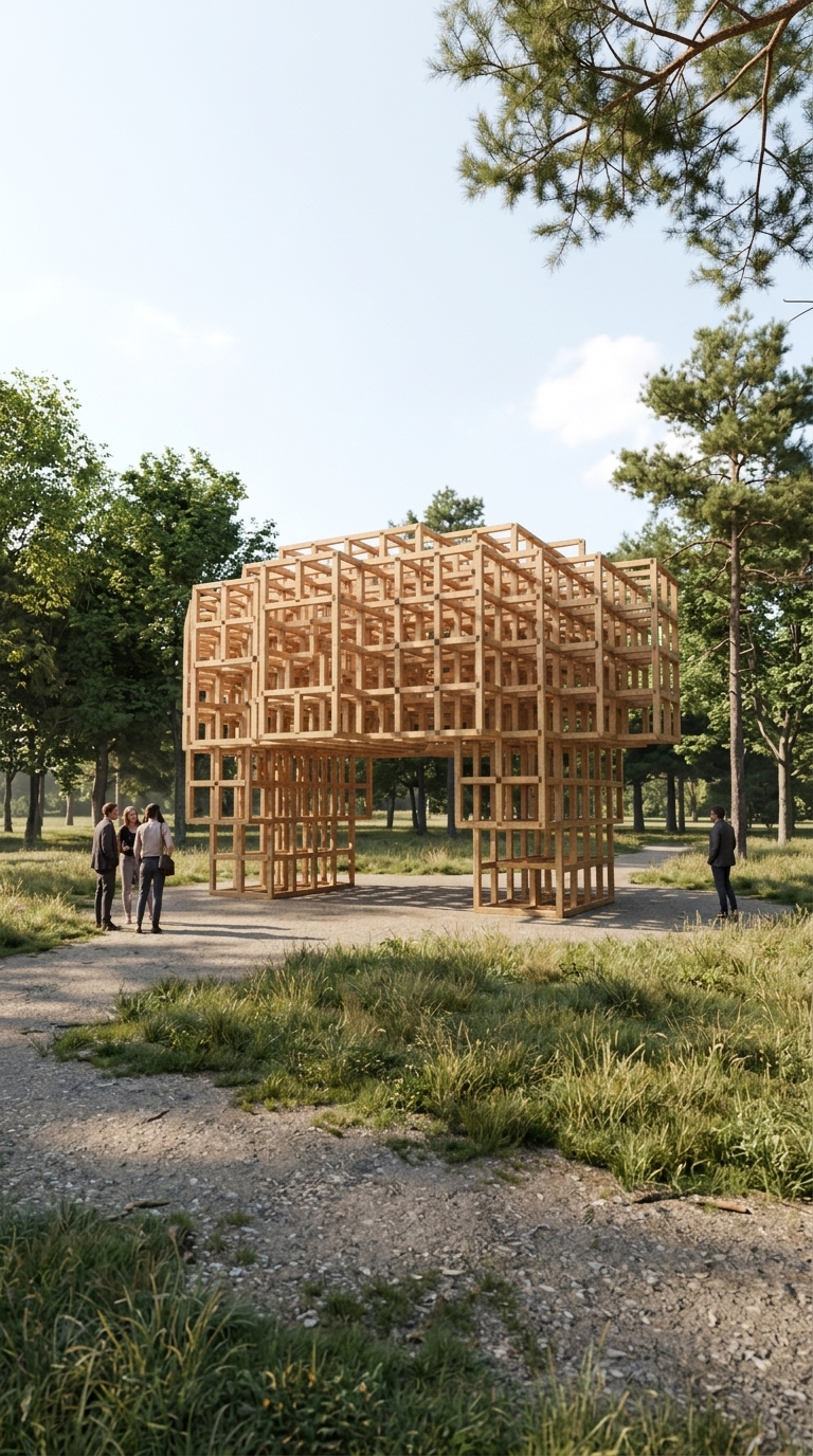
I wanted the supports and canopy to speak the same geometric language. Instead of modelling a set of columns and attaching a separate roof, I started with a growing network. Its local connections would later become timber.
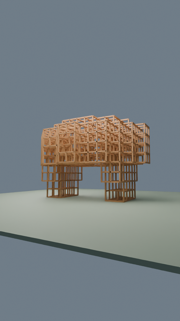
The initial condition is small: eight occupied cells, arranged in two ground-level patches. The space around them is a cubic lattice with a 0.6 m pitch. At each generation, empty positions next to the aggregate become candidates for growth.
Where cellular automata meet aggregation
Here, a cell has a simple state: empty or occupied. It reads its six face-neighbours—left, right, front, back, above and below. The update is synchronous: every candidate reads the previous generation, and all births are committed together. Existing cells persist.
The cellular automaton supplies the local update mechanism. Aggregation describes what it produces: an accumulating set of occupied positions. There are no wandering particles or diffusion-limited random walkers in this particular model.
A general candidate needs one to three occupied neighbours and must pass a probability test. An occupied cell below increases its chance of appearing; positions in the canopy zone get an additional bias. A hash of the seed, coordinates and generation makes the apparent randomness reproducible.
n = occupied_face_neighbors(cell, previous_generation)
p = 0.24 + 0.12 * (n - 1)
p += 0.24 if occupied_below else 0
p += 0.14 if cell.z >= 4 else 0

# Inside the allowed envelope, on the existing frontier:
born = is_leader_cell or (1 <= n <= 3 and seeded_trial < p)
# Commit all births together after evaluating the old state.
Explanatory pseudocode. The download contains the exact rule, integer hash and ordering used in the executed script.
What I imposed—and what developed through growth
The form is not unconstrained emergence. I specified an elliptical envelope, a varying upper height limit and two lower support zones. A central exclusion region keeps a nominal 2.2 m-wide, 2.3 m-high passage clear; the check includes member thickness.
I also included leader cells rising from the support zones and a transverse connection at lattice level five. These cells still grow from the existing frontier, but bypass the ordinary probability test. They encourage the two sides to connect.
Those decisions supply architectural intent. Local interactions and the seeded trial determine the detailed occupation within them. Changing the seed varies the pattern; changing the masks or leader rules changes the design problem itself. Calling the whole result “emergent” without showing those constraints would hide an important part of the design.
One network, one timber system
Once growth is complete, each pair of occupied face-neighbours becomes a timber segment. Every segment has a 0.6 m centreline length and a square 0.08 m section. The same mapping produces the supports and the canopy.
The visible cells are markers for occupied positions. They do not become solid timber cubes: the connections between their centres become members. A member inherits the later birth generation of its two endpoints, so the geometric interpretation remains tied to the recorded growth.
The script evaluates 36 generations, but the last new cell in this run appears at generation 20. That is why the original animation contains pauses. The promotional edit compresses the pauses; it does not introduce a separate growth simulation.
How Relay connected the process
The workflow started with a chat request. Relay connected research, code preparation, local Blender operations and the final visualization through explicit node inputs and outputs.
- 1Start with a question
A chat request defines the experiment and the desired outputs.
- 2Research the method
Perplexity explores the approach; its answer is retained.
- 3Write the growth code
Codex prepares the Blender script and the checks.
- 4Build and animate
Blender computes the aggregate, builds the timber and renders the recorded growth.
- 5Place it in context
Gemini uses the Blender view to make an explicitly labelled site visualization.
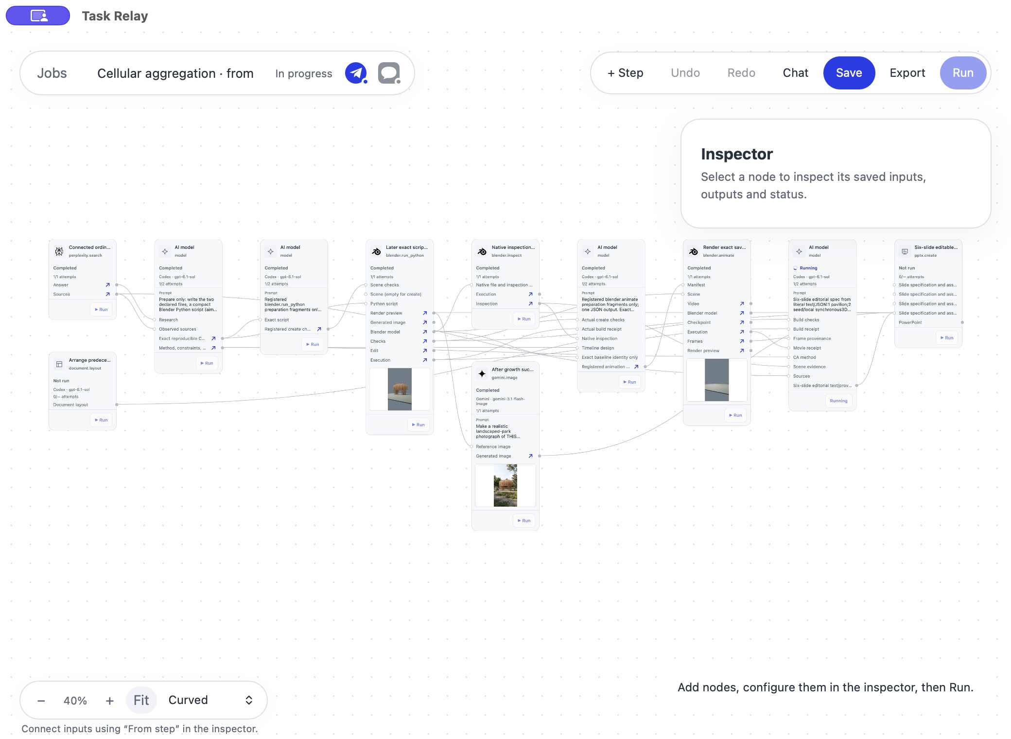
There are useful limits to record. Perplexity's answer was retained, but its source-link collection failed, so I am not presenting that answer as a verified bibliography. The detailed explanation here comes from the executed code. The presentation branch produced an outline but did not complete a PowerPoint export.
Blender produced the model and growth animation. Gemini then interpreted the completed view as a park scene. Its image is useful for atmosphere and scale, but it can alter details and is not a replacement for the model.
What the checks actually establish
The original script checks that the graph is connected, reaches the ground, uses equal-length edges and attaches each later cell to an older neighbour. It also checks that the timber bounding boxes do not intrude into the defined passage. The original Blender execution saved and independently reopened the scene and rendered a preview.
These are geometric checks. They do not establish load capacity, buckling resistance, joint design, foundation requirements or code compliance. The model uses intersecting boxes, not resolved carpentry connections. It is an architectural concept and a method experiment, not construction documentation.
Try the experiment
The exact script and saved Blender scene are the most direct way to explore this result. The Skill helps an AI assistant reproduce or adapt it. The Relay template lets you inspect and compose the tool chain using your own connections.
You can also download the Python script alone. The source bundle's README explains reproduction and variation. It includes a graph-only verifier that needs Python, but neither Blender nor a model call.
The native workflow package passes Relay's import validation; a fresh imported execution has not been tested. You need compatible Relay operations, your own connections and Blender. The optional Gemini step may incur a charge and requires separate approval. Models may write different code on a new run: use the supplied original script for this exact result.
Watch the process
The question I want to explore next is how much architectural variety a small rule set can produce without losing a coherent construction language. The starting point is not another render. It is a change to the rules—and an honest account of what that change does.
Reproduction note, 26 October 2026: the published script's pure growth functions reproduce 733 positions and 1,739 edges. Original native execution: Blender 5.1.2. No new model generation or Blender run was needed to prepare these downloads. Source hashes and scope are included in the package.